
If flection( OffsetLine, OffsetLine, FirstEdge. ParametricAtOpenEdge( SortedEdges, OffsetEdges, 2, OffsetValue)ĭef getOffsetValue( FirstEdge, OffsetLine):Ĭalculate offsetvalue using the offsetline ParametricAtOpenEdge( SortedEdges, OffsetEdges, 1, OffsetValue) ParametricAtEdges( SortedEdges, OffsetEdges, OffsetValue)įor i in range( 1, len( SortedEdges) - 1): Adjust the same offset in your slicer to further carry the printing of the actual.
#Freecad offset how to
pointOnObject( DistanceLines, 2, BaseEdge) How To Draw 3d DiceA computer capable of running FreeCAD Software. # Sketch.pointOnObject(DistanceLines,1,OffsetEdge) perpendicular( OffsetEdge, DistanceLines) Returns True if flection of polyline is negative getSketchPoint( SelGeoId)ĭef _init_( self, Geometry, Number = None): Returns a list containing GeoId's of selected lines and arcs removeEventCallbackPivy( SoLocation2Event.

removeEventCallbackPivy( SoMouseButtonEvent. addEventCallbackPivy( SoMouseButtonEvent.

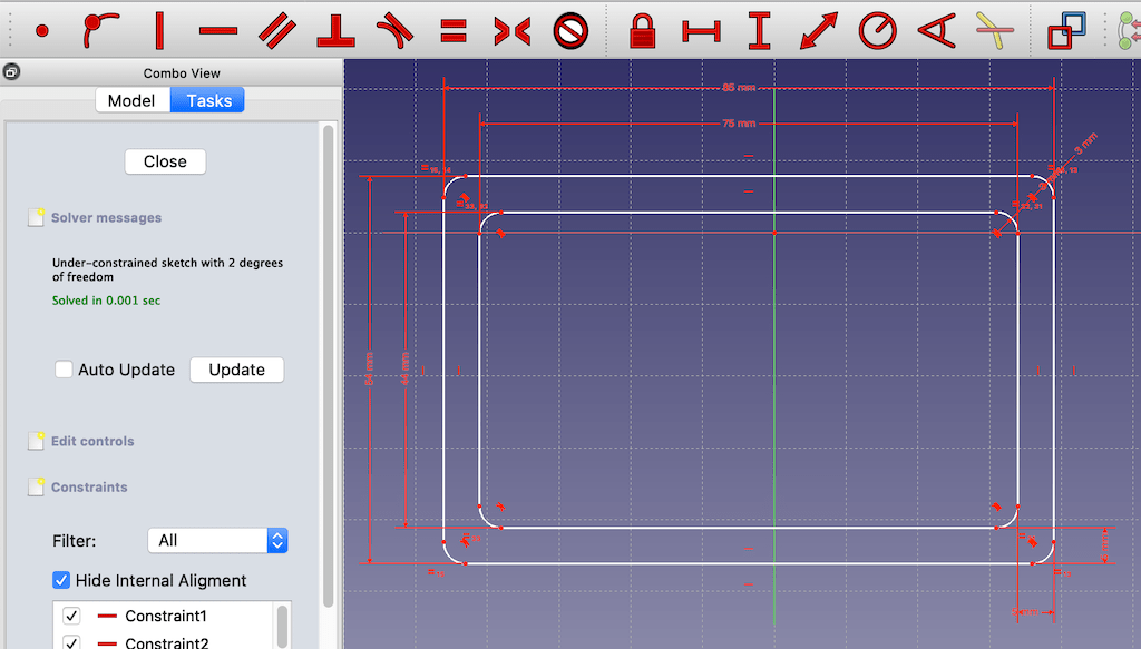
lineTracker( scolor =( 1, 1, 1), swidth = 3, dotted = True) Read selected items and show the offset distance # The major is the year in the LinkDaily branch so that the condition Show offset value using the rubber band.'įrom PySide import QtGui # FreeCAD's PySide!! _License_ = 'License identifier from, e.g. Show value of distance and side (left/right) of the created lines using the mouse. The line chain may be open or closed.Įxisting and created line chain can be draged using the mouse holding the parallelism. All arcs have to be tangential to their neighbours. The existing line chain may be composed of line segments and arcs of cirles. (see example below).This macro creates a line chain parallel to an existing one. Thus boolean operations may lead to strange results. The fill is now a solid, hence the source shape is not a solid.
#Freecad offset skin
Skin creates a new shape around the source shape. Údaje Offset: Distance to offset the faces of the shape.

Cylinder A goes through the FILL whilst Cylinder B only goes thru the FILL and NOT through the source 2D shape. Same shape with a 3D Offset as SKIN and filled offsetįilled offset with 2 Cylinders creating boolean cuts. Same object with thick distance overfilling the front left gap and allowed intersections.Īrbitrary shape ( draft poly as wire ) with a 3D Offset ( ignores MODE param ) Same object with sharp ( intersection ) corners. Object with small offset and rounded ( arc ) corners. On Feb 7, 2022, the FreeCAD project migrated all issues from this site at to our main GitHub repository.


 0 kommentar(er)
